
I am going to build a three-manual stack of keyboards. I’ve bought three M-Audio Keystation 61 ES, which is a very good alternative for organ manuals/keyboards. The weight and touch of the keys are very close to a tracker organ, even though you won’t get the little “edge of resistance” that exists in tracker organ.
I am going to remove the plastic covering. The key stack and the electronics will be mounted in the wooden frame I intend to build. To get an idea of the measurements, I fired up Google Sketchup and created a rough representation to scale of the keyboards. From there, the rest of the construction was pretty simple. Here’s a rendered image from Sketchup:

Since the keys have a square end at the front, the key stack will have a waterfall style (meaning that there won’t be any overhang from the keyboard above). The vertical displacement will be close to the AGO standard. The keyboard design dictates slightly higher displacement, but I don’t think that’s a problem. The keyboards will be mounted to plywood sheets, which then is mounted in tenons in the keycheeks.
Here’s a rendered image from below, showing the “stair” of keyboards:

I intend to extend the lower plywood sheet to the back in order to mount support at the center. The keyboards are very rigid (there’s a metal plate in the center of them), but it doesn’t hurt to make sure I won’t have a problem down the line.
The circuit boards for the two uppermost keyboards will be mounted underneath the plywood sheet. For the lowest manual, the electronics will be mounted right behind the keyboard itself.
Here’s an “exploded” rendered image of the setup:

In front of each keyboard, I will mount a strip of oak. I will mount a strip of felt on the edge that faces the keyboard below.
This design enables me to mount pistons under the keyboards, whether I choose round Klann pistons or the solution found on the organ at the local church:

The frame will be constructed from solid oak, stained in the same color as the bench and the pedal board frames.
The Keystation 61 ES keyboards is USB-based, but I’ve experienced some problems running three identical keyboards on three USB cables. For some reason, one manual (the Swell) is assigned to two different keyboards every single time I restart the computer! The Swell is initially assigned to the correct keyboard. The next time the computer starts, the Swell manual is connected to the Choir keyboard. And the next time I start the computer, the Swell manual is coupled to the Swell keyboard. And so on. Go figure.
The solution is of course to use a single USB-based MIDI module, so that the computer only sees one MIDI input device. I have to do that anyway, since the pedal board needs a MIDI input.
–> NB! Read the update of 30. november 2011! <–
Update 05.09.09
I’ve started work on the keyboard stack today, based on the Sketchup drawings I made. I started by milling and cutting some oak stock to the correct dimension, and then cut the different pieces. Since the piece of oak I bought was too thin, I revised the measurements a bit. The keycheeks are now 35mm wide and 70mm tall.

I checked the pieces for flaws and grain pattern, and then decided which way the different pieces would come together. Note the chalk markings, which is very easy to remove. I then cut a 10 degree bevel at the front of each keycheek. The bevel exits about 15mm from the top.

I then rounded over the upper edge on one piece, and used it as a template for all the other pieces. I used the belt sander, which did not kid around to much…
I then cut a 15mm deep (half the width of the keycheek) slot using the plunge router for the keyboard support pieces. The slot stops 10mm from the front of the keycheeks and is 16cm long. It is 12mm high, measured from the bottom of the keycheek. I used a chisel to square the corners.

I then cut three pieces of 12mm plywood, 16cm by 86,5cm. I used the jointer to make one edge dead straight. That edge will face forward. Here’s an image showing the topmost keycheek and the plywood sheet, giving you an idea of the setup.

I plant to screw the plywood sheets into the slots. The keycheeks will be assembled using dowels, then I’ll just screw them together on the inside using screws and a piece of steel plate or similar.
I did a “dry setup” to check whether my calculations where correct. I placed a keyboard on the different “steps” in order to check if everything looks okay. I used a scrap piece of oak to mimic the wooden strips that will be mounted in front of each keyboard. Everything was spot on!

Here’s an image showing the whole setup.
I will glue and screw a wooden reinforcement to each plywood sheet. I also intend to extend the lowest plywood sheet all the way to the back, since I will mount a USB MIDI interface inside. I also intend to mount a thicker piece of oak at the top, and to make a music stand on top.
Can’t wait to finish the keyboard stack – it is an easy project to do, and it does not take too long either. Pretty cheap too – about 5-6000 NOK. The alternative for me was about 20000 NOK, not including the keycheeks…
Update 19.09.09
The autumn is upon us. Time for another update!
I drilled holes for some wooden dowels in the keycheeks. By carefully aligning the holes, I managed to align the cheeks perfectly. I will not glue the keycheeks together in order to be able to disassemble the keyboard stack. Instead, I’m considering using a bolt through the cheeks, screwing them together. If I chose that approach, the bolt will most likely be mounted from underneath.
Here’s an image of the keycheeks. The shortest one (topmost manual/keyboard) is upside-down. I accidentally drilled a hole in the longest cheek too far forward. The foremost dowel is offset to the side of the cheek; this is self-explanatory if you look at the topmost cheek:

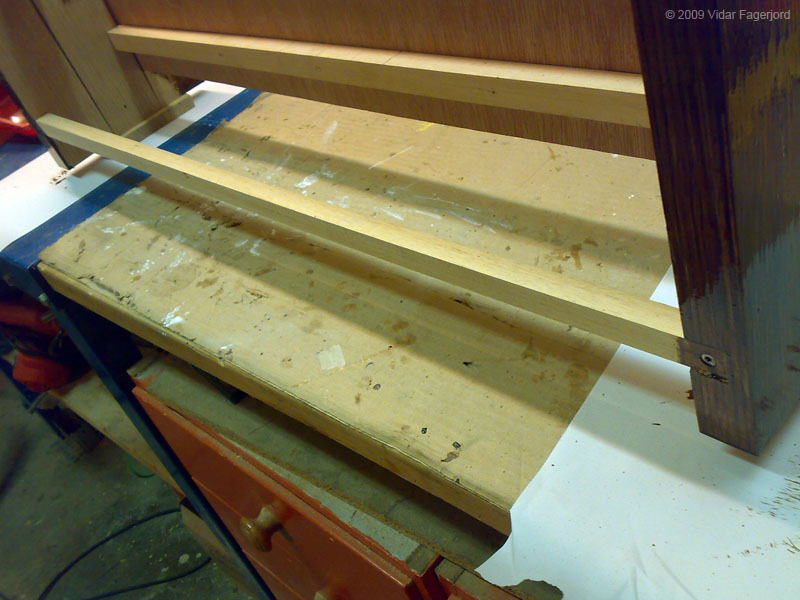
I decided to add a support structure to each of the plywood sheets where the keyboards will be mounted. I mounted a strip of Ramin hardwood (still have some scrap pieces from the pedal board) using screws. I might glue them too, but I do not like to rush things…
In the image below, the third manual has been reinforced, with the second manual soon to follow.

The lowest manual is more tricky. You can’t add anything underneath it, since that space is reserved for your legs! Not to mention should this keyboard stack be placed on a table (which it actually will be until I’ve made the console). Luckily, the M-Audio Keystation 61 ES keyboards I’m using for this project has plenty of space directly beneath the front portion of the naturals. I therefore mounted the reinforcement on top of the plywood sheet, directly underneath the keys.

Time for a test! I whipped out the keyboard I’ve removed from the casing and placed it into the stack. FAIL!!! The stack was about 1.5mm too narrow! I solved the issue by using the thicknesser to remove 1mm from each keycheek, from the side facing the keyboards.
Perfect fit!
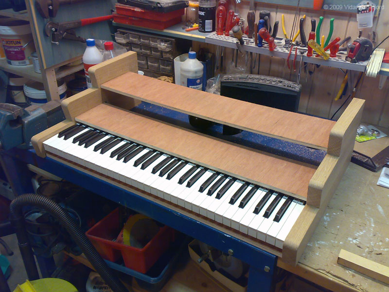
I then ripped three 5mm (0.19685″) oak strips (I cut them about 6mm thick on the band saw, used the thicknesser to trim the strip down to 5mm. I planed the cut side of the “strip master piece” between each cut). Using the keyboard as a guide, I placed the strips in front of each “step”. They was initially a tiny bit too wide, so I just wedged them in place. I did trim them down a bit so that they are a tiny amount too narrow, allowing them to expand during changes in humidity and temperature. This will look GOOD! Especially when there’s some dark brown stain and brass screws in place!

Here’s a shot from the side (note that the lowest support bar is missing)

And finally a shot with the strips in place and the keyboard placed at the second level:

Now I need to cut holes for the screws that fastens the keyboards to the stack. I plan to cut 5mm slots for each screw, enabling me to adjust the keyboard from side to side in order to get equal distance from the keycheeks to the first / last key.
I also intend to cut an oak board which will be mounted on the top / back of the third keycheek. I also need to make a horizontal support bar at the back of the lowest cheeks, cut grooves for a plywood sheet that will cover the rest of the bottom – and make back covers. At least that’s as far as I’ve planned. I also need to make a note stand and find a way to securely mount it at the top.
Can’t wait to get the keyboard stack home! It certainly will look good. I would’ve gone for light oak in a heartbeat, but I decided not to since lacquered oak tends to be a bit yellowish over the years. I also wasn’t completely sure that I would be able to use the same type wood (american red oak), so brown stain it is.
Update 24.09.09
And brown stain it has been for sure! The last coat of stain is applied, now it’s time for a few coats of clear lacquer after I’ve drilled the holes for the screws that secures the keyboards in the stack.
Since the keystack will be mounted in a console, I decided not to cover the bottom of the stack. Instead, I mounted a piece of Ramin wood as a spacer. This solution stiffened the whole contrapment, and ensures equal distance between the keycheeks.
Here’s an image of how I made the holes for the counter-sunk screws that secures the oak strips in front of the keys:

I marked the placement of all the screws, transferred the marks to the other strips (making sure that the screws line up), drilled the holes and counter-sunk the holes so that the screws becomes flush with the surface.
Then I stained the parts. Here’s coat #1:

and coat #2:

The stain I’m using is expensive, so I didn’t paint more than I needed. No reason to paint areas that will never show…

Note that two images up, I’ve painted the front of the plywood support sheets. I did that in case the gap between the keys and the oak strips should be big enough to show what’s underneath. Doesn’t hurt to be a LITTLE picky…
Now I need to drill holes for the screws that secures the keyboards, add a few coats of clear lacquer, install the keyboards and find a solution on how to mount the electronics. I also need to make a music stand and find a suitable light for the music stand.
The keystack will be finished very soon! Can’t wait!
Update 01.10.09
I mounted two strips of plywood on the inside of each stack of keycheeks in order to secure the cheeks together. The strips also acts as a mounting point for a back cover (more on that later on). I will use an L-shaped metal bracket near the front of the middle cheeks to secure the first and second cheeks together. The bracket will be mounted to the cheek and to the plywood sheet that supports the keyboard.

I also intend to mount a plywood shelf inside the keystack, where the USB MIDI interface will be mounted. I’ve discovered that Hauptwerk doesn’t keep the assigned settings on which manual goes where. By using a MIDI interface, that problem goes away. Each manual will be connected to the MIDI interface via standard MIDI cables, as I’m using the electronics from the keyboards. No need to over-complicate things. I’ll write more details on the setup when I am finished with the keystack.
I took the stained keystack home for a couple of coats of clear lacquer. And I also got the first decent photos in the same run! The camera on my mobile phone is okay, but my Canon DSLR (EOS 30D + 24-105 f/4 L IS USM for you photo freaks) is superior in every aspect!

An image of the three “steps” in the stack:

Here’s a couple of images showing the stack with the key covers assembled with brass screws:


Somehow, the image above reminds me of the song
“stairway to heaven”…
A detail image of the cheek / key cover. Note that I’m in the middle of applying stain here:

I measured where the screws for mounting the keys to the plywood “step”, drilled holes and counter-sunk the holes in order to get far enough into the plastic fasteners on the keys. I am actually using the screws that was used in the keyboard. This image shows the uppermost manual with the keys mounted, upside down and from the rear. The springs on the keys are clearly visible:

Here’s an image of the two PCB’s and how I’m going to mount them. I made a square hole in the plywood “step”, fed the flat cable and the black wire through – and the rest is fairly simple:

To the right, you’ll spot the USB connector, the MIDI connector, a foot switch connector and the power switch. The small PCB holds a power connector for +9V DC. The PCB’s will be screwed to the plywood with plastic insulation under the PCB “just in case”. Crude, but simple!
The pitch bend wheel, modulation wheel, switches and volume slider is placed on separate PCB’s. I intend to utilize the modulation wheel for swell pedals and crescendo pedal. I am not sure if I can extend the wires down to the actual pedals, or if I have to make some sort of mechanical linkage. Oh well – that problem will be solved in due time!
The next image shows the assembled third manual. Note the light-colored oak strip just aft of the sharps – a little design detail I came up with. I am going to mount dark red felt between the keys and the light strip to close the gap. More on that later, as I don’t want the felt to come near the workshop. There’s wood chips and dust everywhere!

The lowest manual is more difficult, as I can’t mount the PCB underneath it. Instead, I’ll extend the flat cable and the black wire, and simply mount the PCB on a plywood shelf aft of the first keyboard.
Not much work left now – except for the music stand. This part of the project is fairly simple to do, and I’ll get a great looking keyboard stack dirt cheap compared to the commercial alternatives!
Update 05.10.09 – Finished!
Well – not quite finished, since I still need to buy a MIDI interface, make a shelf for it and fasten the back cover. But in all other aspects, the keyboard stack is finished and working great!
I glued some 5mm dark red felt to the oak strips to fill the gap between the strip and the keyboard below. I chose this approach, since the felt will give way for the 1mm vertical displacement of the rear of each key. And it looks good too, which to be honest was the main goal…

I cut a strip of felt from the roll, applied contact cement to the felt and to the bottom of the oak strip. When the glue wasn’t sticky anymore, I carefully applied the felt strip, adjusting it along the way so that it was placed right on the edge.

And the finished result:

I’ve received quite a lot of emails asking about the keyboards, so here’s some images:

The backside of the keys

right side; note the two “feet” and the gap underneath the
playing surface of the naturals

The underside

And the last image shows the electronics. As you can see, the modulation and pitch bent wheels are connected to a single connector, but are mounted on separate PCB’s. The volume slider is on its own PCB, as are the three buttons and LED’s. The brown PCB is the mainboard, and the small PCB to the far right is the power input PCB. The keyboard works just fine with just the mainboard attached.

I mounted the PCB’s underneath each “step”. I screwed the button PCB’s and the power input PCB’s directly to the assembly. The button PCB is needed should you need to assign a different channel to a keyboard, or change any other settings.
I am planning to utilize the modulation wheel from each keyboard for the swell pedals and the crescendo pedal. I plan to test if I can extend the wires, or if I have to make a mechanical linkage of some sort. I’ll cover that when I get to that point.
And as you can see, all the keyboards are now installed in the stack. And they work beautifully! They have a great feel, and the vertical displacement seems to be just perfect. In short, I think I can summarize this part of the project in one word: success!
Here’s some images for your enjoyment:


And finally: here’s my setup as of October 5th 2009:
I still need to make a music stand, but the keyboard stack is fully functioning.
Here’s what’s left to do:
- Mount the back cover
- Mount pistons or switches for general combinations (not a priority)
I will place the keyboard stack, the monitor, the speakers and the computer on a desk to make the setup more representative and to accommodate the pedal board. I am planning to use the winter months planning how my console will look like.
This has been a VERY fun part of my project, and as it turns out: a pretty easy one at that. And I’ve managed to make my three-manual keyboard stack for about 1/4 of the price compared to the closest commercial solution. That being said, I do not have any pistons nor do my keyboard have the tracker touch feel. But as an economical alternative, this setup is pretty good! I should also point out that I’m fortunate enough to have a well-equipped workshop available.
Hopefully, I’ve inspired you and demonstrated that if you put your mind to it – there’s nothing you cannot do yourself! If I can do this, so can you.
Or – if you think that such a project isn’t for you, I highly recommend that you check out the commercial solutions out there. I do not care how you manage to get there, but get yourself a nice setup so you can enjoy playing a virtual pipe organ in your home!
A big thank you to all of you that have sent me emails (and continues to send emails) with questions, suggestions and encouragement. Let my website and the images of my work be a humble way of giving something back.
Thank you!
Update 20.05.10
I did not need to buy a USB interface after all. The keyboards are connected to the Hauptwerk computer via USB. Each manual uses MIDI channel 1, but since Hauptwerk recognizes each manual as an individual input device, that’s no problem.
The keyboards works flawlessly and have a very nice feel and touch. I am considering adding a 4th manual – but that means that I have to go back and change the layout to overhanging AND sloping keyboards in order to make the keystack playable and comfortable. Time will show…
I decided to drop the back cover since the console will make it redundant. The pistons, however, is a completely different story. I’ll eventually fix that, but since pistons aren’t that big of a deal (toe pistons are far more important), I’m in no rush.
Update 30.11.11
Here’s an answer to an email I received asking about the problems I experienced with the keyboards (the issue was not resolved after all, despite what the 20th may update says):
This issue was present with HW version 3.something. Do not know if version 4 is affected, but it is likely. The error is probably caused by the fact that 3 Keystations equals 3 identical inputs, only differed by a number or letter assigned by the computer. However, there’s no way to control which keyboard is assigned to which input when the computer is switched on.
I resolved the whole issue by adding two 3 port MIDI interface (daisy-chained into one interface with 6 inputs). The MIDI OUT from each keyboard goes to a MIDI IN on the interface. The interface has 4 inputs with different addresses to each input, so if the lowest keyboard is connected to MIDI IN 1, that’s not going to change. Ever. With HW 4, I do not have to select which input goes to which keyboard. I just use the auto-detect feature on each keyboard for each sample set, and I’m good to go.
All keyboards has the same MIDI channel, but each keyboard (including the pedal board) has their own, unique input. Insanely simple! I use the Roland UM-3G.
The UM-3G modules can be daisy-chained to each other. You can connect 3 in each chain, giving a chain with 9 MIDI IN and 9 MIDI OUT. The first one is connected to the computer. The next one is connected to the first one and a selector is set to “2”. The last one is connected to the second one with the selector set to “3”. That’s all there’s to it. The input list will then be something like this:
UM-3G(1)
UM-3G(2)
UM-3G(3)
UM-3G(4)
UM-3G(5)
UM-3G(6)
(…)
And in my setup, the pedal board is UM-3G(1) (MIDI IN 1). The lowest keyboard is UM-3G(2) (MIDI IN 2) and so on. Since the lowest keyboard is physically connected to the second MIDI IN on the first UM-3G, it will never change unless I swap the MIDI cables around.
The uppermost keyboard is connected to MIDI IN 1 on the second UM-3G, but since it is daisy-chained the computer sees it as MIDI IN 4. Can’t go wrong there!
I suggest you do the same. This setup work FLAWLESSLY! No hiccups at all. Just power the computer, wait for the organ to load and go nuts.